
 CN / EN
Wenzhou University Flapping-Wing UAV
Client:
Dr.Chen Si and his research team at the School of Mechanical and Electrical Engineering, Wenzhou University
Paper:
Aerodynamic efficiency enhancement effect of the energy capture technique on a flyable flapping wing rotor system
Application:
Motion Capture, Rotorcraft, Algorithm Validation, Energy Harvesting Springs, Natural Frequency, Lift Efficiency
Micro-biomimetic aircraft has become a major research focus in recent years due to small size, strong maneuverability, low detectability, low noise emission, high stability, and high aerodynamic efficiency at low Reynolds numbers. Around a decade ago, researchers proposed a new structure of flapping-wing rotor (Flapping Wing Rotor, FWR) combining the characteristics of bioinspired flapping wings and rotorcraft, the feasibility of which has been validated over the past few years. However, the lift margin of FWRs has not yet reached the level required to carry any useful payloads (e.g., miniature cameras or small packages), limiting their practical application. While previous studies have explored the lift issues of FWR, no research has been conducted to experimentally address the reduction of energy consumption due to inertial force through the use of energy capture mechanism (such as a spring). Additionally, while it is known that setting the twist angle to 40° can significantly improve the lift of FWR, the effect of the variation amplitude of the twist angles on the FWR remains unclear.
To address these issues, Dr.Chen Si and his research team at the School of Mechanical and Electrical Engineering, Wenzhou University, conducted the study titled "Research on the Enhancement Effect of Energy Harvesting Technology on the Aerodynamic Efficiency of Flapping-Wing Rotor Systems," which aims to investigate the impact of energy capture mechanism and twist angle variations on the lift of FWR, with the goal of providing new insights into the payload capacity and application range of FWR. The results were published in the renowned engineering journal SCIENCE CHINA Technological Sciences.
1、Research Plan:
The research team designed and manufactured a 19.2g FWR model. In the first part of the study, three different mechanical parameters of springs (detailed in Table 1) were selected and installed on the FWR. These springs were designed to capture the energy generated by inertial forces during the upward stroke and release this energy during the downward stroke to accelerate wing motion, thereby reducing energy loss caused by inertia. The second part of the study involved setting three groups of wings with different twist angle ranges (10°–50°, 10°–70°, and 10°–90°). Using a motion capture system and lift measurement system, the aerodynamic and kinematic performance of the FWR was tested under these two experimental modules to analyze the effects of twist angle variation and spring size on FWR motion parameters and lift efficiency.
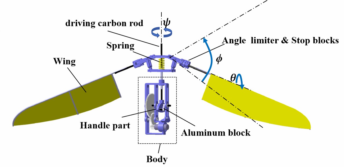
Figure 1: Distribution of the energy capture mechanism on the FWR
Table 1: Mechanical Parameters of Energy Capture Spring

Innovations and Advantages:
1. The introduction of energy capture springs to optimize FWR lift performance from an inertial energy loss perspective.
2. The setup of wings with three different twist angle ranges to explore the influence of twist angles on FWR lift.
3. The assembly of a 37.8g FWR flight system, achieving stable take-off mission and hovering action during experiments.
2、Experimental Validation:
The experiment consisted of a lift testing system, flight system, and motion capture system. The CHINGMU optical motion capture system, based on 24 MC4000 cameras and CMTracker software, accurately recorded the FWR's physical motion to ensure valid experimental data. As shown in Figure 2, the high-speed cameras capture the time-varying positions of six fluorescent feature points on the wing surface. Then, the twist motion, rotary motion, and stroke motion curves are calculated by the CMTracker software.
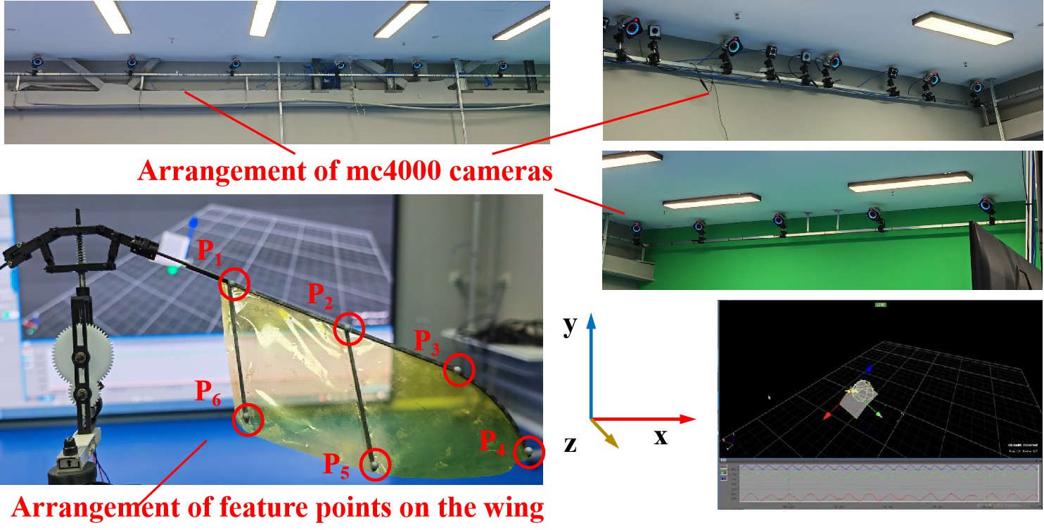
Figure 2: Motion Capture System for the FWR
The lift measurement system, as shown in Figure 3, included the FWR, the load cell (YZC-191),the power supply, the signal amplifier, the signal acquisition card (NI USB-6008), the synchronization circuit, and a personal computer. After calibrating the pressure-to-output voltage relationship of the sensor, the voltage signals were recorded through the signal acquisition card and amplifier to capture the forces acting on the load cell. These signals are transmitted to the computer via LabVIEW software for further data analysis.
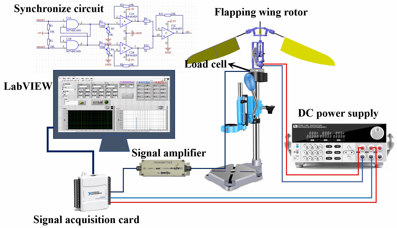
Figure 3: Components of the FWR’s Lift Measurement System
Comprehensive analysis of the data from the motion capture and lift testing systems (Figure 4) showed that under the conditions of a 5-V input voltages and a 10°–70° rigid twist angle, the FWR exhibited high flapping frequency and achieved the greatest average lift of 29.24g. Beyond that, Figure 5 shows that under the case with 10°–50° twist angles , the FWR with springs exhibited higher flapping frequency and greater lift compared to the springless FWR, as well as a slight reduction in energy consumption, thus improving lift efficiency. Moreover, the twist angle amplitude and rotational speed of the FWR showed a positive correlation with the spring stiffness coefficient and input voltage.
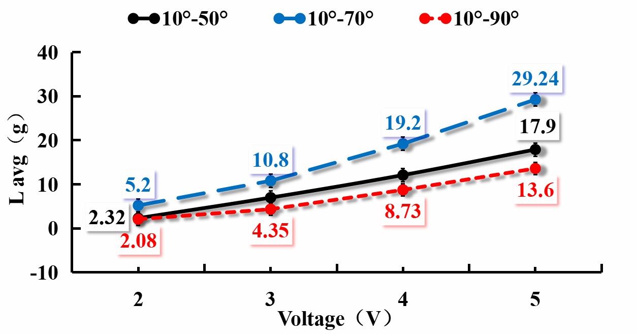
Figure 4: Average Lift of FWR with Three Twist Angle Configurations
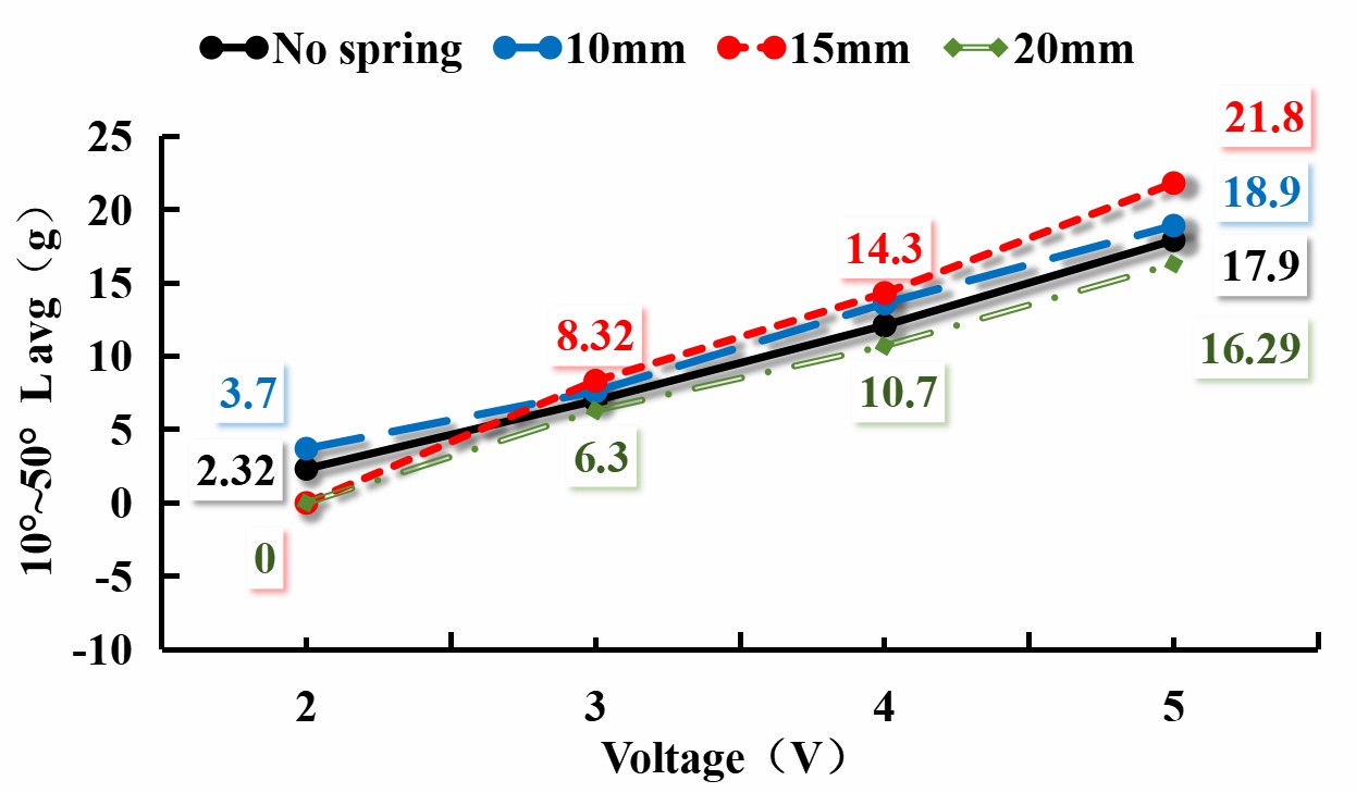
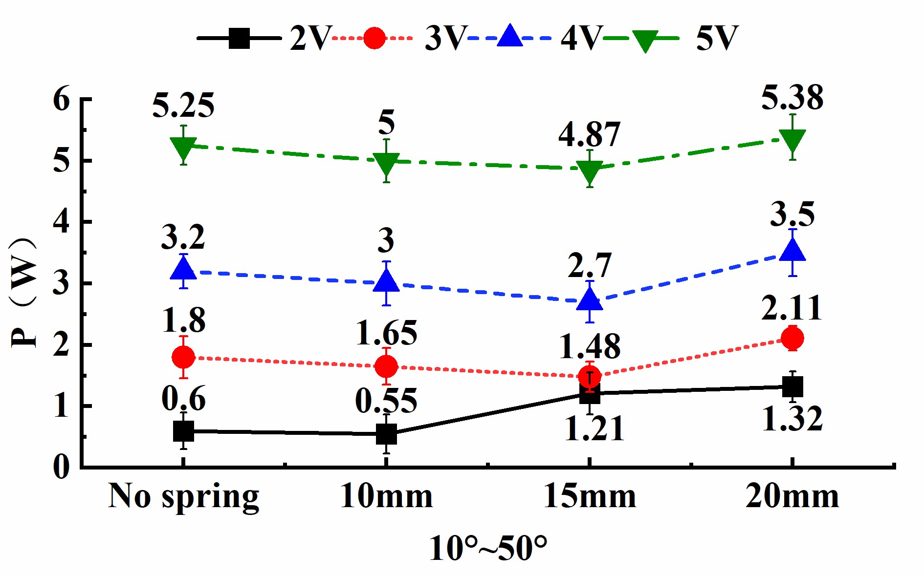
Figure 5: Average Lift and Electrical Power Consumption of FWR with Three Springs under 10°–50° Twist Angle
To further illustrate the effect of spring resonance frequency on lift enhancement, the Fourier transformation was used to convert the twist curve into the frequency domain. The results (Figure 6) showed that when the main frequency with maximum amplitude approached or coincided with FWR structure’s resonance frequency, the lift enhancement effect was more apparent.

Figure 6: Fourier Transformed Main Frequency vs. Spring Resonance Frequency
The flight system, based on the original mechanism, with a total weight of 37.8g. As shown in Figure 7, the system included a flight control integration board (O1Studio), a rotating servo, and two batteries. One 3.7V battery powered the flight control board, while the other 7.4V battery powered the coreless 8520 motor. Notably, the research team used a custom-controlled control surface to ensure the system’s stability during flight.
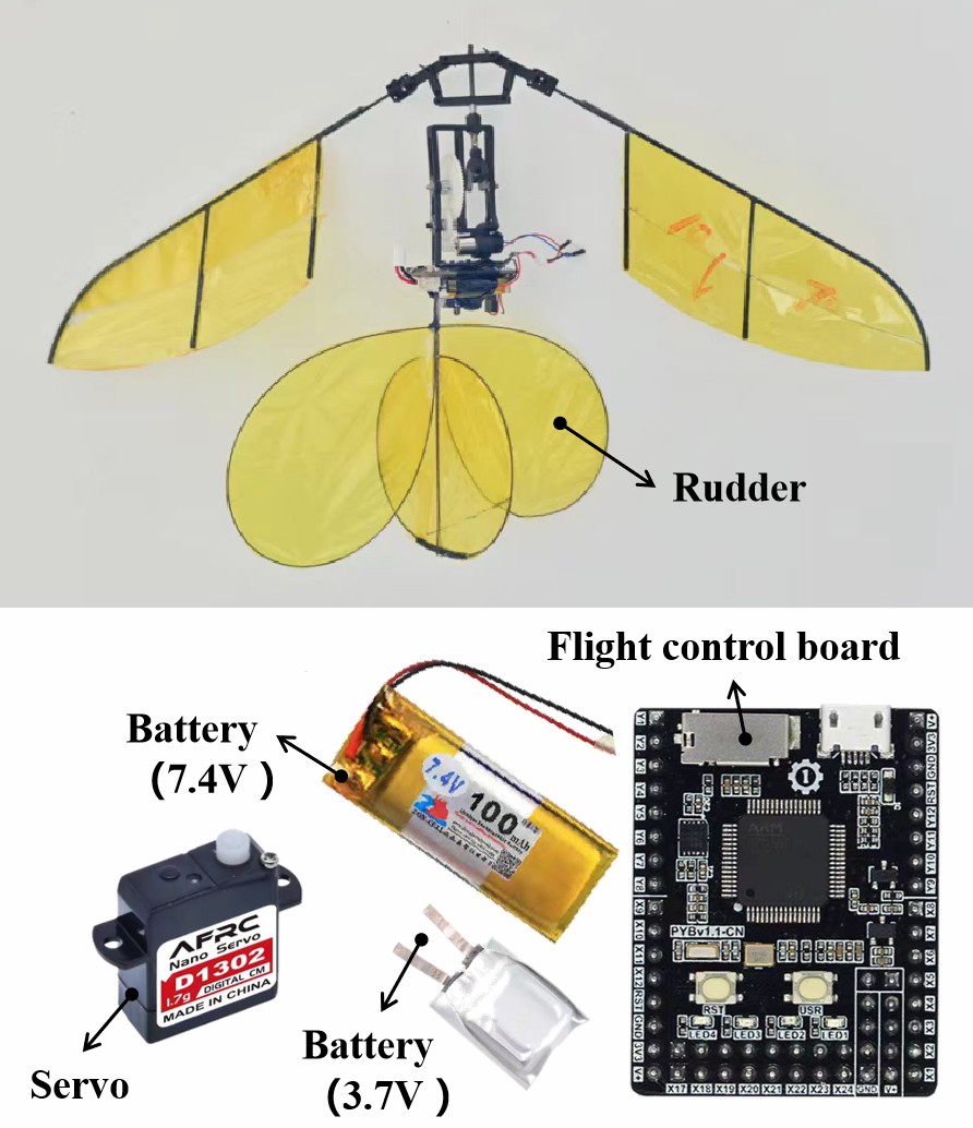
Figure 7: Structure and Components of the Flight System
As experimental results showed that the FWR system had sufficient lift margin and successfully maintained hover for about 3 seconds. Eventually, due to limited battery power, the FWR system descended slowly.
3、Experimental Results:
The study concludes that both the selection of a 10°–70° pre-set twist angle and the application of springs can enhance the lift efficiency of the FWR,providing two viable strategies for further improving the aerodynamic performance of FWR systems.
References:
1 Fuller S, Yu Z, Talwekar YP. A gyroscope-free visual-inertial flight control and wind sensing system for 10-mg robots. Sci Robot, 2022, 7: eabq8184.
2 Phan HV, Park HC. Mechanisms of collision recovery in flying beetles and flapping-wing robots. Science (1979), 2020, 370: 1214–1219.
3 Jafferis NT, Helbling EF, Karpelson M, Wood RJ. Untethered flight of an insect-sized flapping-wing microscale aerial vehicle. Nature, 2019, 570: 491–495.
4 Helps T, Romero C, Taghavi M, Conn AT, Rossiter J. Liquid-amplified zipping actuators for micro-air vehicles with transmission-free flapping. Sci Robot, 2022, 7: eabi8189.
5 Chin Y-W, Kok JM, Zhu Y-Q et al. Efficient flapping wing drone arrests high-speed flight using post-stall soaring. Sci Robot, 2020, 5: eaba2386.
6 Dong X, Li D, Xiang J, Wang Z. Design and experimental study of a new flapping wing rotor micro aerial vehicle. Chinese Journal of Aeronautics, 2020, 33: 3092–3099.
7 Chen L, Cheng C, Zhou C, Zhang Y, Wu J. Flapping rotary wing: A novel low-Reynolds number layout merging bionic features into micro rotors. Progress in Aerospace Sciences 146 2024.
8 Chen S, Wang L, He Y et al. Aerodynamic Performance of a Flyable Flapping Wing Rotor With Passive Pitching Angle Variation. IEEE Transactions on Industrial Electronics, 2022, 69: 9176–9184.
9 Li Q, Ji A, Shen H et al. Experimental Study on the Wing Parameter Optimization of Flapping-Wing Aircraft Based on the Clap-and-Fling Mechanism. International Journal of Aeronautical and Space Sciences, 2022, 23: 265–276.
10 Nian P, Song B, Xuan J, Zhou W, Xue D. Study on flexible flapping wings with three-dimensional asymmetric passive deformation in a flapping cycle. Aerospace Science and Technology, 2020, 104: 105944.
11 Salami E, Montazer E, Ward TA, Nik Ghazali NN, Anjum Badruddin I. Aerodynamic Performance of a Dragonfly-Inspired Tandem Wing System for a Biomimetic Micro Air Vehicle. Front Bioeng Biotechnol, 2022, 10: 787220.
12 Wu J, Yan H, Zhou C, Zhang Y. Unsteady aerodynamics of a micro flapping rotary wing in forward flight. Aerospace Science and Technology, 2021, 111.
13 Chen L, Zhou C. Linearized Aerodynamic Modeling of Flapping Rotary Wings by Rotating the Leading-Edge Suction. AIAA Journal, 2021, 59: 1–7.
…………
